Hi, I'm Ava Rizzico
Mechanical Engineering and Design major at Northeastern University, and Red Vest at Northeastern's First Year Engineering Learning & Innocation Center (FYELIC)

Hi, I'm Ava Rizzico

Mechanical Engineering and Design major at Northeastern University, and Red Vest at Northeastern's First Year Engineering Learning & Innocation Center (FYELIC)
C Monster, 2024
FIRST Robotics Competition, Team 2084: Robots by the C's 2024 robot for the Crescendo FRC game. This was my high school robotics team's robot that I worked on during my senior year, as the Programming and Senior Captain.
Shrammer
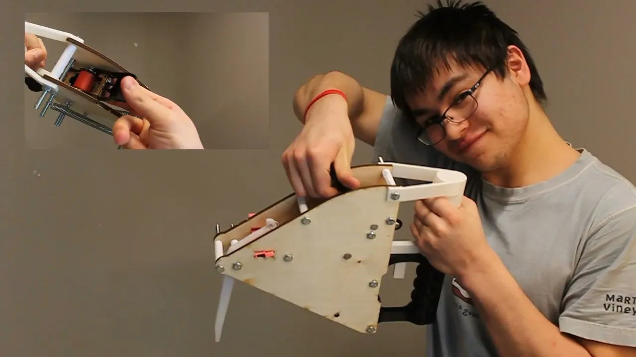
An accessible alternative to the traditional hammer: this mantis shrimp inspired device is powered by a simple ratchet and spring, and can easily punch a nail into the wall in a single shot.
Crabs in a Bucket
A labyrinth and strategy based board game in which players play as crabs racing to collect things they care about before escaping a metal bucket.
Hanging Planters
Hanging planters are a great way to save space in a small apartment, but how can you grow plants such as herbs or flowers that require water drainage in a hanging pot?
Video Game Curriculum
For my senior high school project, I wrote a curriculum which teaches students how to create video games in the Unity game engine, which is currently being used at Manchester Essex Regional High School.
Interested in working with me?
I am currently searching for my Fall 2026 Co-Op.
Feel free to contact me below.
Shrammer
Sparked by a group project in my Cornerstone of Engineering class, the Shrammer is a spring-loaded hammer, inspired by the Mantis Shrimp, and built to aid elderly and disabled autonomy. Costing no more than $53 to manufacture, this device could easily bring independence back into the lives of many people who are unable to use traditional hammers due to strength issues.


Inspired by the punch of a mantis shrimp, while the Shrammer takes a few seconds to properly load by cranking the ratchet, the swing of the arm can easily punch a nail into a wall. This allows for a single strike to be able to do any job that a traditional hammer would take a few strikes to achieve.
How it Works
By cranking the ratchet, the strap wrapped around the ratchet is attached to a spring, which thus puts tension on the spring, priming the mechanism. The spring is attached to the upper end of the arm, while the lower end of the arm presses up against the trigger. Thus, as soon as the trigger is pulled, the mechanism will actuate, with the spring recompressing and the arm swinging forward.

Our Process

Unfortunately, after our initial test, the acrylic arm snapped, likely due to its poor impact strength at our speed. We expected it to be stronger than MDF but our suspicion was proven false. So, I researched what materials could withstand high impact stress, and came up with a few options: aluminum, and polyeurathane. While aluminum would be preferred for a realistic scenario, it was not within our budget to have a custom cut piece of aluminum in our build. Thus, I sourced a cutting board from our local hardware store made of polyeurathane, and using a combination of a band saw, drill press, and printed/cut solidworks drawing, I produced a new arm.My groupmate Asher was in charge of filming the video below, which thouroughly explains the design process we went through, and contains a tutorial for how to use the device. Part of the exploded view mentioned above is also included.

Our assignment required that we exhibit an exploded view created using SolidWorks in our final video, so I ported the files from Onshape into SolidWorks by saving each part as a SolidWorks part file, then assembled them in an assembly file, adding bolts and nuts using the SolidWorks toolbox. After finalizing the design (showcased below), I laser cut the final side panels out of plywood, because MDF had worked well for previous prototypes, and MDF is just a product of wood, but proper plywood looked nicer than MDF. I used the arm and trigger from the second prototype which had been laser cut out of acrylic and glued together, because it worked perfectly and didn't need any updates. Asher again 3D printed the handles on a Bambu Lab printer, which allowed for minimal imperfections and a smooth finish. The spacers were also 3D-printed, but on a prusa printer, because their particular quality didn't matter as much because there were so many of them.
The design phase of this project took shape through a collaborative and iterative design process. Throughout the prototyping phase, however, my job was task distribution and some manufacturing and CAD. Our initial prototype was a quick cardboard model which I built, and was relatively weapon shaped, which we decided to change upon feedback from our class and professor. The second prototype that I designed was much more triangular, with an aim to have handles above and below the mechanism. I modeled it in Onshape and laser-cut the side panels, arm, and trigger, while my groupmate Asher 3D printed the handles. The trigger and arm were laser-cut acrylic, which we thought was stronger than MDF (but not free), while the side panels were cut out of MDF (which was free).

The triangular models were quite bulky, thus I refined it into a much more rounded and ergonomic shape in the CAD document.The handles were reprinted by Asher, and this time featured grips, as well as a new width to fit the new side panels, both of which I designed in tandem with my groupmate Zach. I planned out how all the components would fit together, as well as the designs of the handles, arm, trigger, and side panels in an Onshape assembly, which functions nearly identically to a SolidWorks assembly. Zach measured their own hand to figure out the dimensions of the grip part of the handle. Onshape's online nature allowed for easy collaboration and sharing of ideas and files regardless of device limitations.


Hanging Planters
The initial motivation behind this project was personal. As a college student moving into a suite with a kitchen, I was excited at the idea of adding fresh herbs to my food. However, with the rising costs of living, I was debating going without seasonings on any of my food. That is when I stumbled across herb seed packets at my local hardware store, and decided to just grow my own.In a small apartment, space is a challenge. With no lack of window space, but a complete lack of windowsill space, hanging planters were sounding like the best choice, until I realized that most herbs need to be potted in a planter that can drain. Nearly all planters on todays market don't have any way to drain water out of them without the water just ending up on the floor: hence I designed my own, in a solo project motivated by the cost of groceries.

Process
There are various ways to get water to drain out of a planter, but it is important that the rope which the planter hangs from doesn't block the access to the water. My initial idea was to utilize a mouth-like hole underneath a grate near the bottom of the planter, so the planter could be split into two sections: one for the plant and dirt, and the other for the water drainage. The water could pass through the grate, but the large pieces of gravel at the bottom of the dirt couldn't, and the gravel would hold the dirt above it and prevent it from washing through the grate.


I am currently working on further designs of hanging planters for my other herbs: chives, oregano, and rosemary. I will likely continue to use some form of grate to seperate the water from the soil, however where the water goes next will vary by design. I am hoping to create a water collection that hanges on a hinge, which can thus allow the basin to tip and pour out water while not tipping the section of the planter where the plant is located.

While this system worked well, it didn't work for the herbs. Herbs need deeper soil, and that design didn't allow for that. Thus, I created another version, this one with a screw on water catch, so that in case it overflowed, it would just bottom water the plant instead of getting all over the ground (which was another issue the previous design had).I also ended up repurposing the previous planter design for a string of pearls plant, which doesn't require very deep soil. However, this later proved to be too shallow a pot for even the string of pearls plant, so I ended up redesigning it to be a bit deeper, resulting in a more rounded shape of the pot.

Want to print your own?
I have the files to each planter design I have created thus far available for purchase on my Creality page.
I also have a few other free useful item files available, such as replacement strap adjusters for backpacks.
Crabs in a Bucket
This board game was created for a group project in my Design Perspectives class. My group of five decided to make a labyrinth-based board game which we eventually dubbed "Crabs in a Bucket", due to how the gameplay reminded us of crabs scurrying around the inside of a child's bucket after being caught. It is a strategy game at heart, with quite a bit of randomness thrown in to spice it up and make each game a bit different.

My Process
My role within this project was to build the board and the walls. This required me to consider tolerances between the walls and the board itself, as well as manufacture each piece, and design the layout of the labyrinth.I began by researching labyrinths, and decided upon making a hexagonal design, so that I could break it into triangular tiles which would be assembled together to form a hexagonal maze. Then, after designing the labyrinth in SolidWorks, I planned out each item's location, and each crab's starting position, to make sure that each crab would travel the same distance to each item. Because of the tileable nature of the design, this was pretty simple, because it meant the distance between each corner or center of each tile was the same between tiles.

Then, I laser cut the board out of MDF, and slowly watched the project come together. While there were a couple errors in the design (a missed hole and a missed engraving to mark where part of a wall would go), those errors didn't impact the performance of the project.Another part I was responsible for was the resin printing of the crab pieces. This part consisted primarily of sourcing the file, confirming its approval with my groupmates, and then getting it printed in the Northeastern CAMD Ryder makerspace.


Once the design was finalized, I had to make sure that the pegs for each wall fit the holes in the board. I did some research for tolerances in 3D printing and compared them to the tolerances used in laser cutting, and discovered that roughly a 0.02 in tolerance should work for our purposes.I 3D-printed the walls, sanding and painting them as I went, first with two layers of grey and then with two layers of silver.

The removing of the supports from the finished print was easily one of the most physically difficult parts of this project. The supports for the prints were about the same diameter as the legs of the crabs, so it was extremely difficult to not accidentally snap the legs or arms of the crabs as the supports were being removed.While several crabs were lost in the process, we did eventually get the full six crabs finished and ready for painting. The painting was done with acrylic, and then finished with clear nail polish to prevent scratching.
How it Works

These items are placed around the board in such a way so that no crab has to travel any farther than another, and are indicated by colored dots matching the assigned crabs' colors, as well as writing of the item's name behind the space. There are also cards of each item, which players collect as their items, and discard an Action card as they do so.Each player starts with 3 Action cards, which allow them to build walls, remove walls, move walls, move other players, and other fun actions. At the start of their turn, they can chose between playing a card or rolling a die to move their crab.The game ends when a player collects all their items and goes to the center of the board. When in the center space, with all their items, they win.
Players begin by chosing their crab, each of which has a Character Card and a game piece that matches the Character Card. No crab has an advantage over one another: the only differences are how we describe each crab, and their color. On their character card, a list of 3 items is given which the player must collect before they can "escape" the "bucket".

Video Game Curriculum
Video games have been a big part of my life for as long as I can remember. When I was making my own for a personal project my senior year of high school, I noticed that a lot of students took interest in my work and wanted to learn how to do what I was teaching myself: making video games. Thus, I took it upon myself to write a curriculum on how to do so as my Senior Choice Of Related Experience project (SCORE).I have written curriculums in the past for sailing classes, but teaching in a pure classroom setting was something that was relatively new to me. Additionally, the curriculums I had focused on as a sailing instructor were for students ages 6-12, not 16-18. Regardless, I knew the same principles of balancing kinesthetic, visual, auditory, and written/reading are required in order for anyone to be able to obtain any skill.Because I believe that everyone should have a right to education, I have made this curriculum free to download. It is designed to guide a high-school class, and can either be handed out to students to follow individually, or be followed and/or modified by a course instructor. It can also be followed independently by anyone who is interested in learning how to make video games using Unity. It is important to note, however, that this curriculum was written in 2024 and therefore utilizes the 2024 version of Unity.
The C Monster
In high school, I was part of the Manchester Essex FIRST Robotics Team 2084, Robots by the C. Each year, we would make a new robot (always named the C Monster) for the FIRST Robotics Competition (FRC). In 2024, I was the programming and senior captain, which meant that I was responsible for the majority of the programming of the robot, event registration, and some coordination and communication with the school. Each year, upon receiving the challenge through the FIRST Robotics Competition kickoff event, we would design a robot from scratch to complete the tasks as efficiently as possible.In 2023, I was the mechanical captain, leading the creation and implementation of all mechanisms. However, in 2024, all of the programmers graduated, and we were unable to recruit more, so the task of programming the robot fell onto my shoulders as the senior captain.

This year's robot specialized in picking up orange rings known as notes and shooting them into a high goal. My primary task for this project was writing the swerve drive code, which had never been done by our team before and has been reused every year since. Additionally, I coded the specific functions of this year's robot, oversaw all of the subteams as senior captain, led the implemenetation of LEDs on the robot to indicate shooter speed, and found new sponsors for our team. Using my mechanical knowledge, I was also able to aid the new mechanical captains when needed with the swerve drive and implementation of the shooter, intake, and intermediatry mechanisms.

Brainstorming
In 2024, the event was named Crescendo: a music-inspired event, in which robots had to shoot bright orange rings into a high goal, place them carefully in the low goal, and hang from chains before the game ends.As senior captain, I facilitated the brainstorming sessions we held after the kickoff event. This session was very important to me, because previous years, the captains had decided what each mechanism would be and how they would work without input from the rest of the team. I refused to let that happen again.This session entailed sitting the entire team down immediately after the kickoff event to brainstorm ideas on sticky notes and poster paper for each mechanism that the robot would have to have. In this case, the mechanisms were a shooter, intermediary device, and intake for the rings, a climbing mechanism, and a drivetrain.

While the idea of a swerve drive was set in stone since September (and the kickoff was in early January), it was still important to listen to other students' input on ideas such as drivetrain shape and size. We ended up deciding as a team on a smaller robot that used a simple flywheel based shooter and wheel-based roller intakes.While the other two captains (Robin and Kate) and I did have the ability to veto ideas that were either unfeasible or went directly against the rules of the competition, every other idea remained on the table. This allowed for some creative problem-solving, especially from our younger members.
Prototyping
My shooter prototype, meant to demonstrate how a shooter could utilize a pneumatic piston to shoot a ring, is exhibited on the right. While we did not end up going with this design, because pneumatics take up a lot of room in the robot, it was important to our process of elimination of ideas from the brainstorming session. This was not the only prototype that was created: some students showcased their ideas with popsicle sticks, others with legos. Any method of exhibition was encouraged.

While the prototyping of the swerve drive code in the fall didn't utilize PID or the gyroscope, I spent the rest of the build season integrating those systems into the programming. This allowed me to create autonomous driving and shooting sequences, so our robot could score points during the autonomous period of a match (during which no-one is allowed to manually drive the robot).Meanwhile, the rest of the team worked on prototyping a flywheel shooter utilizing recycled robot parts from previous years.

Much earlier, in the fall, the team began prototyping the drivetrain and I began programming it. The team built a very simple drivetrain with only the necessary electronics, while I began researching how I should program our swerve drive. I recruited help from a previous mentor, Sam, who coached our team when we went to the FRC World Championship in 2018, and also helped write WIPLIB, the software used to run programs through all the robots within the FIRST Robotics Competiton. My only experience with programming prior to this project had been making a video game in Unity, and taking an AP Computer Science class in which I learned Java basics. I had never even touched Github. However, with the help of Sam, I managed to learn how to utilize libraries, what a Proportional Integral Derivative controller (PID) is and how to use it in code, and how to integrate the gyroscope into the code as well in order to create a field-oriented swerve drive.

PID Errors

About two weeks before our first competition, I encountered an error where the wheels would turn uncontrollably whenever we attempted to drive the robot, exhibited above. I knew this was due to errors in my programming, because this error occured immediately after pushing new code that was supposed to make the driving field-oriented instead of robot-oriented. This was necessary because it would allow the driver to drive straight regardless of the starting orientation of the robot, and was integral to creating autonomous driving sequences. However, an error as big as this occuring this late in the build season could have prevented our participation in any competition.

Luckily, after adjusting some PID values, I was able to tune it to a point where the wheels would flip 360 degrees whenever the robot changed direction. After reading through my code various times, I realized this was because the size of the robot that I was referencing from another team's code was much larger than our robot, so the wheels thought they were in different locations than they actually were. This allowed me to completely solve the issue of the wheel jittering by the middle of the week before our first competition, because this line of code with the size of the robot was the root cause of the issue, and properly tuning the driving just allowed me to diagnose it more easily.
Competition 1
Our first competition, while not incredibly successful, was fantastic for stress testing our robot. Through this, we learned to fine tune our shooting for the ring into the high and low goals, and to give time to allow our shooter to properly spin up before shooting the ring. While I was able to quickly whip up some code that would display the speed of the flywheels on the dashboard, it wasn't nearly clear enough to be sufficient.

Between Competitions
The struggle with the flywheels led to the week between competitions being dedicated to adding LEDs to the robot. The LEDs visually indicated flywheel speed, successful note pickup, as well as various other states of the robot. I once again had to rush to teach myself how to program LEDs, while simutaniously walking a new member through how to do so. This way, the team would not have zero programmers after I graduated.


After stress-testing the robot at the competition, we learned that the wheels that were part of our intermediary device were unnecessary. Additionally, the polycarbonate that was along the bottom of our intermediary device had too high a coefficient of friction which made the polycarbonate stick to the notes. By rubbing various materials on the notes, we determined that surprisingly, duct tape had the least friction against the foam notes. Thus, we coated the intermediary polycarbonate in duct tape (seen above).Additionally, we did not have a climber, so some of the younger members designed a climber during this phase of improvement.
Competition 2
Our second competition went much better than our first. Despite our climber's makeshift appearance, it worked perfectly. The only thing that was keeping us from rivaling the top teams was that our shooting had to be manually lined up. Being the only programmer on my team, I did not have time for anything non-essential such as that.


The LEDs allowed us to see the status of the flywheels mid-game, which made our shooting much more consistent than it was during our first competition. In the image on the left, you can see Robin, myself, and Ian (left to right) watching the robot and its LEDs for the right time to shoot a note into the high goal.Thanks to the improvements we made between competitions, we were high enough ranked to become the alliance captain of the 8th ranked alliance (pictured below). While this was the lowest ranked alliance, we hadn't been an alliance captain for at least 5 years, so this was a historic achievement for our tiny, scrappy team of 20 students and two mentors, facing off against teams of 100+ students and mentors.
